This post is part of a series I intend to write this weekend which fully explain most aspects of some of my bigger projects, so hopefully they make a little bit more sense than my normal posts.
The flip side is that they’ll be a lot more technical.
Introduction
I’m a member of one club at school: Robotics. Every year we compete in FIRST Robotics Competition, which is aimed at high schoolers building autonomous/teleoperated robots. This year the challenge is to throw frisbees into rectangular goals at each end of the playing field.
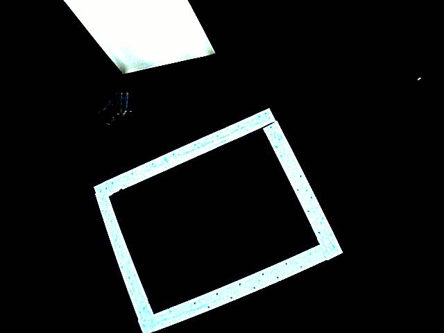
So we decided that we’d build a program that could use the camera feed from the robot to automatically aim the robot at the target. This is made easier by the fact that the targets are lines in retroreflective tape, and we have a high-power LED array pointing at the tape. After we monkeyed with the camera’s gain settings, we got a relatively clear image:

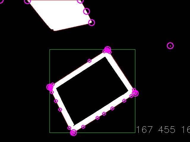
Which we have to convert to a couple of different variables, such as bounding box, angle from center, and distance from the target center line, which I’ll represent graphically as:

Robot Control System Architecture
As with most projects, there’s multiple different layers of architecture involved. The topmost is how this program fits into the rest of the robot control system.
The robot control system consists of an IP camera, mounted on the robot, a cRIO, which is a FPGA-based computing device, also mounted on the robot, both of which are connected to a wireless access point which we connect to with the drive station computer to control the robot.
My program sits on the drive station computer as a (C++) server daemon process separate from the rest of the drive station software. The daemon talks directly to the IP camera to fetch the imaging feed, and it presents a network API which the cRIO connects to in order to receive the processed imagery data.
Server Daemon Architecture
The next architecture layer is how the server daemon is internally laid out. Internally there are three threads, each dedicated to one of the main tasks. The three main tasks are:
- “networking”: This thread pulls the latest imagery data from the camera, and saves it to disk. This thread is freewheeling, pulling data as fast as is possible in order to keep the latest imagery on hand.
- “processing”: This thread processes the images gathered by the previous thread. When this thread is ready to process the next image, it locks on a mutex which is normally held when the networking thread is currently writing data to the file. When networking starts pulling the next image, it momentarily unlocks the mutex to allow processing to copy the file to it’s internal storage.
- “server”: This thread manages the server API. Clients connect to the sockets generated in this thread. Note that this thread can’t do the same mutex trick as networking, because it is not allowed to block, but it does do a similar trick by trying the mutex.
The Processing Pipeline
Now, the part you’ve all been waiting for. How we convert from the first image to the second image.
The first thing we do is condition the image. In this step we resize to a 640×480 image, convert to grayscale, apply a Gaussian blur, and then threshold the image.
The next step is to find the edges. This is done with the OpenCV Canny edge detector, which returns us an image with the edges highlighted. We then take this image and turn it into a “point cloud”: All of the pixels which are lit (i.e. are an edge) are added to a giant list of points which consists of the point cloud.
Then what we do is split this master point cloud into smaller point clouds, based on their relative groupings in the image. In the future this step and the one before it can be merged for performance optimization, but for now they remain two separate steps.
Actually, they remain three separate steps. The splitting of the master point cloud takes place in two steps: Creating new point clouds, and then merging clouds that are close together. Creating new point clouds is done by looping through every point, and determining if it is near one of the already defined point clouds. If it is, then the point is added to said point cloud. If not, then a new point cloud is created which contains that one point.
After merging the clouds nearby, we are left with a series of point clouds, which we apply the convex hull operator to. The convex hulling operation removes over 95% of the points we have to process in later steps. The points returned by this operation are rendered as small purple circles in the above image.
Now it’s just a matter of converting the point cloud into 2D quadrangles, followed closely by 3D rectangles. The first step is done by finding the four corners, which I implement by searching through the convex hull of the point cloud and finding the four vertices with angles closest to 90 degrees. These vertices are marked as big purple circles.
These four corners make a bounding box of the rectangle, which is marked with the green square.
These four points are also fed into the rectangle3D framework, which processes the points to form a best guess for the matching 3D rectangle.
Rectangle3D Solver
This solver is deceptively simple. One could do high level math to figure out the reverse affine transformation to figure out the best match.
Or one could do an “iterative solver”.
I first determine that the four known 2D points define lines extending from the camera to infinity through the 2D point, at some set plane distance. I used 1 as the backplane distance, but as long as the FOV is taken into account correctly these lines can be defined.
The next step was to define a function that found the “squareness” of some 3D rectangle. That is, how closely the angles four corners match 90 degrees (RMS).
Then we start with some arbitrary distances for guesses for the initial points of the rectangle. Note that a distance along one of the lines defines a point in three space, so four distances along four lines defines a quadrangle.
For each corner, we try moving it some small distance away from the camera, check to see if the solution becomes “more square”, then move it a small distance closer to the camera, and choose the better solution. Then we repeat.
I realize that this is not the best way to do it, but with properly tuned variables (i.e. how small is “small”), and a well-defined breakpoint, it exits within a short period of time.
Once we have four points which define a rectangle in three-space, it becomes trivial to do calculations such as center-line distance, etc.
And that is how I convert from the top image to the bottom image.
Possible Future Work
In the future, I would like to implement a little bit more user flexibility. Right now, most of everything is hard coded. I’d like to add support for multiple cameras, multiple different clients, each with it’s own configuration. Some will be looking for rectangles, some for triangles, some for circles, etc. I’m thinking that each camera pipeline can have it’s own fetch/processing threads, which feed to a single server thread handling the clients.
Likewise, I’d like to clean up the network API. Right now there’s a large schism between the official documentation and what is actually implemented. This is bad.
Source Code
This project ended up on my GitHub account:
https://github.com/lkolbly/FRCVision
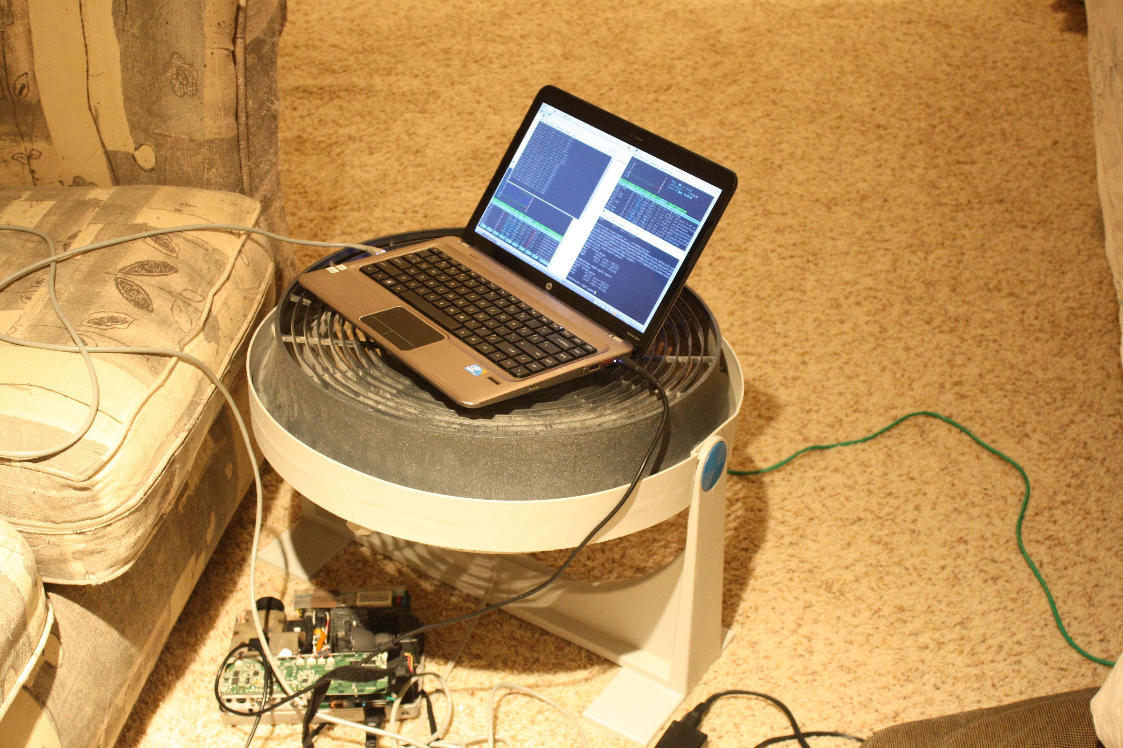
No story today, but I think I have invented perhaps the greatest laptop cooling stand of all time:

