So, when I moved my blog’s hosting I hadn’t planned on not posting for 6 (or 7 or 8) months. But that’s how it went down, and it’s okay because I’ve been working on several cool projects (FreeCiv AI, spectrometers, 3d printing, and learning Verilog, among others) and I’ve been in several cool classes (Cryptography and Astronomical Instrumentation come to mind).
But, I will start posting here monthly again, and I have enough projects I should be able to write about a cool project every month for the rest of the year (monthly strikes a decent balance between weekly and never).
On to this month’s project. It’s actually the project from early April, but there was a bit of a delay in posting this.
A couple of weeksmonths ago I got a Mojo v3 board, which is the Teensy of the FPGA world - small, simple to use, and works on Linux. Some differences include that instead of the several MB ‘duino toolchain, you have to use the several (15) GB Xilinx toolchain. The Mojo has a small ATMega which does bootloading, ADC, and USB serial. Word of warning, though, is that the onboard LEDs are literally painfully bright. PWM dimming of LEDs was one of the first tutorials I did when learning Verilog.
I also have, from a birthday past, one of those swanky resistive touch TFT display shields that Adafruit builds for the Raspberry Pi (I promise I’m not sponsored, I just used a lot of different brand names in this project).
Ah, you see where this is going, good.
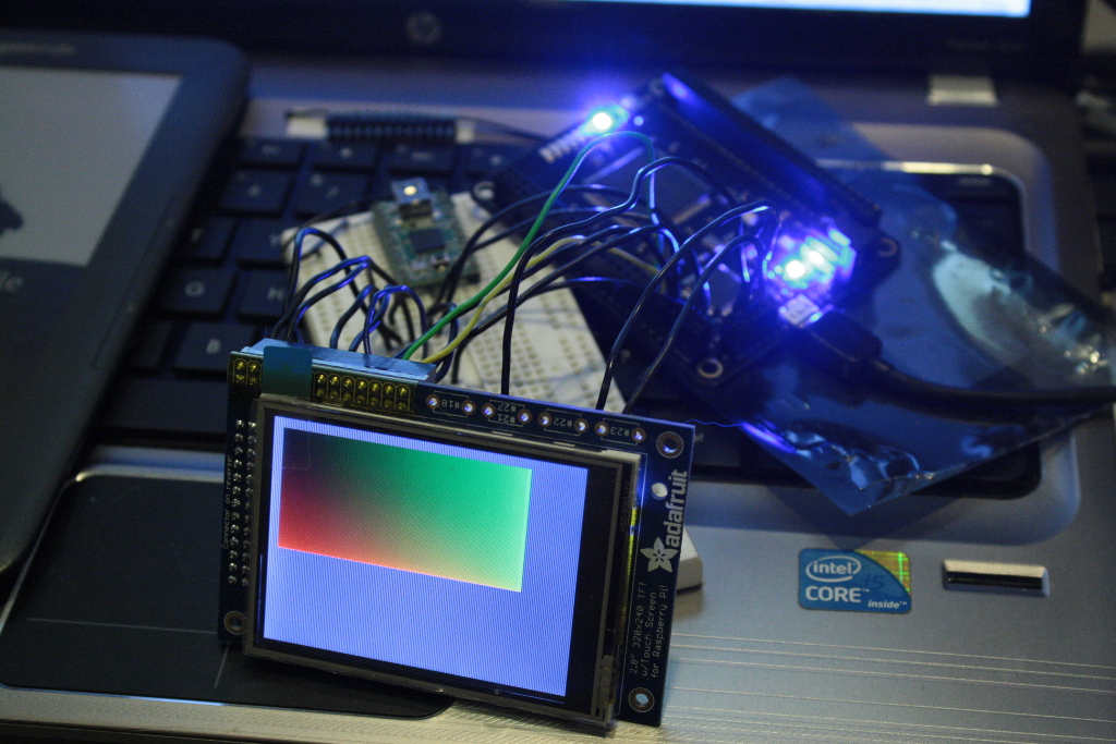
So after building a simple RPN calculator for my Mojo a few weekends ago (using USB serial for the interface), I decided to build something (haven’t decided what yet) using my touchscreen. So far I have the display driver:

One of the first problems I ran into was finding the appropriate pinouts and specs. Adafruit sells about a dozen different TFT touchscreens, some with their longer pin header, some with capacitive touch, and so on. My screen looks exactly like the screen in the learning article they have on their website, except that one is capacitive and mine is resistive. Regardless, I found all the right datasheets and started hooking it up. I had to go through a breadboard because there’s 5 ground pins and 4 voltage pins (at two different voltage levels) on the display, and the Mojo doesn’t have that many.
So don’t worry, the Teensy in the background is unconnected, I’m not secretly driving the display through it. It’s just from a past project. There’s also a trimpot hidden on the breadboard behind the display, which in principle I could use for something.
Fortunately, the TFT display can be driven using a 5 wire pseudo-SPI interface, which is the simplest interface in the world, and we can ignore the Master-In-Slave-Out (MISO) pin (because we don’t care what the display has to say).
Unfortunately, the interface is only pseudo-SPI, because there’s an extra D/CX line which is used to determine whether the master is sending a command or a data. So I had to build a SPI interface module in Verilog, which in truth was quite fun (and relatively easy, too, I think I’m getting used to this programming paradigm).
The next step was to build the monstrosity that boots and sends data to the screen. The boot sequence was a little tricky to figure out, because it’s hidden away in the “register default” section of each individual command in the 233-page reference manual. The Sleep Mode setting says that the default is Sleep On, but it says nothing about needing a software reset or needing to issue a Display On command, and so forth. For reference, you can get away with issuing a software reset followed by a Sleep Out command followed by Display On (with appropriate delays between the two).
Then, to actually write the data, you have to issue column/page set commands before the memory write. The display provides an interface wherein the drive writes into a defined window of the display, which is handy for things like bitmap blitting: I should be able to build a window of a specific size at the bitmap location, and then just spew the contents of the bitmap onto the SPI line. Someone suggested Space Invaders - this would be perfect for that.
Of course, this being Verilog, this is all done using a state machine which goes through the appropriate states and keeps track of how much memory has been written.
Now it’s all said and done, I can write a gradient out to the TFT screen. My next step is to interface with the touch controller, and maybe build out missile command or something.
